ON THE BENCH
Welcome to part two of the development of the i-Switch robotic mower area changer. In my last blog I explained how this project came about and the main goals I wanted to achieve. This blog post explains some of the stages involved in getting a working prototype for testing.
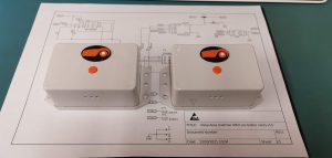
First of all, I draw up some sort of electrical schematic (a wiring diagram broken down into sections) to work from, this lays out the basic workings for the design and allows for easy adjustment notes as you go. Then once you have that you can then start to assemble your test circuit on a breadboard. A breadboard is a way of connecting components together without soldering or creating a PCB.
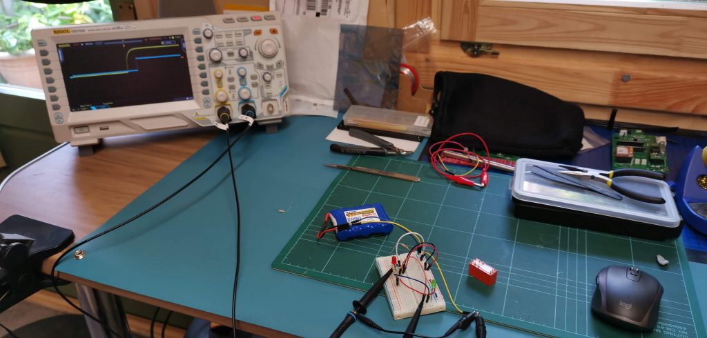
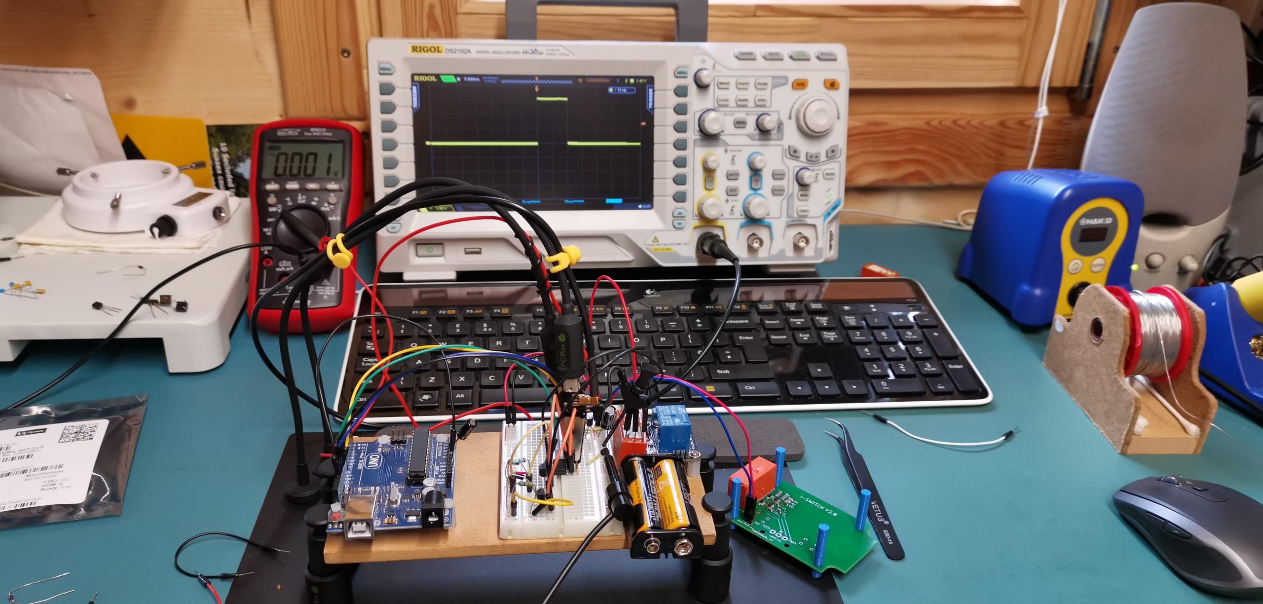
Breadboard circuit hooked up to the oscilloscope to measure switching speeds
Although you have to go through this breadboarding stage it is not my favourite part as the messy wiring and general fragile nature of it is not the way I like to work, but it saves a huge amount of time and money testing things before you commit to a fully manufactured PCB.
The i-Switches use high quality, fast switching relays to toggle between two areas, these were picked because of their long life, fast switching and because they are a “Latching” relay. This is the key to getting a long battery life (more on that in a later blog). So the next stage was to get the relay to operate with the minimum amount of power and fast so it could be switched while the machine was mowing if necessary. After doing a couple of different versions I decided the best way would be to use a microcontroller to control not only the relay switch timing but also the direction and power management. For those that are wondering, a microcontroller (or MCU) is a small computer containing everything it needs to run inc memory, ROM & RAM, clocks for timing (not our clock time but time in micro & nanoseconds etc for time-critical functions like communication etc), ADC (analogue to digital converters) and much more. This can be programmed using the C programming language to not only time the relay switching, but check the last switched area and memorise it after changing and power down the circuitry to save battery. This will only require a single button operation so keeps things very simple to use.
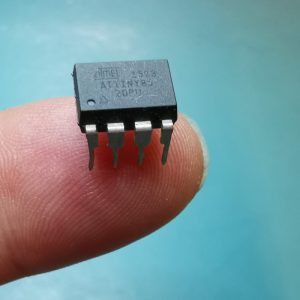
“a microcontroller (or MCU) is a small computer on a single IC” The wonders of modern technology!
So after putting together a test circuit and writing some test code it was time to try the prototype. This I do by using an electronic power supply set to the correct voltage and with current limiting on so if there are any unexpected short circuits (this can happen easily on a breadboard!) the power supply shuts down before any damage happens. Once I know it is all ok I then check it using the battery supply it would end up using so I know it’s been tested and works correctly with the battery power it will end up using in the finished switches. From this point on I start converting all the schematic drawings to a PCB using software on a computer, in my case I use Fusion 360 which allows me to design a pcb and any CAD models for 3D printing (more on this to come).
In the next blog, I will explain some of the prosses in the PCB design and how I use modern 3D printing to make some of the parts for the iSwitch.
If you would like to buy one for your installation click the button below and happy robo mowing!
-
 i-Switch Mk3£114.00 inc vat
Comments